MCXE31 Basic Secure Boot Example#
This example demonstrates how to create a signed MBI (Master Boot Image) for MCXE31 devices using Basic Secure Boot mode. The resulting image will be programmed into the internal flash via the blhost tool.
1. Prerequisites#
SPSDK is needed with examples extension.
pip install spsdk[examples](Please refer to the installation documentation.)This example uses MCXE31B freedom board
HSE firmware must be installed on the device
import os

from spsdk.utils.jupyter_utils import YamlDiffWidget

# This env variable sets colored logger output to STDOUT
%env JUPYTER_SPSDK=1
# Set a magic for command execution and echo
%alias execute echo %l && %l
%alias_magic ! execute
env: JUPYTER_SPSDK=1
Created `%!` as an alias for `%execute`.
WORKSPACE = "workspace/"  # change this to path to your workspace
INPUTS = "inputs/"
VERBOSITY = (
    ""  # verbosity of commands, might be -v or -vv for debug or blank for no additional info
)
MBI_CONFIG = (
    INPUTS + "mcxe31_mbi_config.yaml"
)  # MBI configuration file. Used to generate signed MBI image

SIGNED_MBI = WORKSPACE + "mcxe31_mbi.bin"  # Final signed MBI image
ADKP_KEY = INPUTS + "adkp.bin"  # ADKP key for provisioning

HSE_FW = INPUTS + "mcxe3xb_hse_fw_0.5.0_2.55.0_pb250324.bin.pink"  # HSE firmware

# Flash addresses
APP_ADDRESS = "0x400000"
VERIFY_ADDRESS = "0x00400fC0"

# Communication parameters
BLHOST_CONNECT = "-p COM21"  # COM port - change this to your actual COM port
1.1 Compile an Application#
Blinky LED XiP application is used in this example.
To use a custom application follow the steps:
Download the NXP MCUXpresso SDK from NXP web site (https://mcuxpresso.nxp.com/)
Open the example in your favorite IDE.
Compile your application using the corresponding target. The resulting binary must be copied to input folder.
2. Basic Secure Boot Overview#
The MCXE31 Basic Secure Boot (also known as IVT-based secure boot) mode is implemented based on the AppBL header and ADKP, and the HSE firmware enables only one application core at a time. The length of AppBL header is 64 bytes and the application code address starts from “AppBL header start address + AppBL header length”.
Key features of Basic Secure Boot:
Single Core Operation: Only one application core is enabled, as specified in the Image Vector Table (IVT)
GMAC Authentication: Uses GMAC (Galois Message Authentication Code) based authentication with a key derived from the Application Debug Key Provisioning (ADKP)
Mutual Exclusivity: Can only be used when SMR/CR (Secure Memory Region/Code Region) based Secure Boot is not in use
IVT Structure: The boot process relies on the Image Vector Table to define the application entry point and authentication parameters
This approach provides a balance between security and simplicity, making it suitable for applications that require authenticated boot without the complexity of advanced secure boot mechanisms.
3. Initialize Flashloader#
The MCX-E Flashloader is a configurable flash programming utility that operates over a serial connection on MCX-E device. It enables quick and easy programming of MCUs during final product manufacturing.
Before we can communicate with the device, we need to initialize the flashloader using J-Link. In this example, we’ll use the J-Link debugger to establish communication.
Interface |
Pin function |
Pin |
|---|---|---|
LPUART |
LPUART0_TX |
PTA3 |
LPUART0_RX |
PTA2 |
|
LPSPI |
LPSPI0_MOSI |
PTB1 |
LPSPI0_SCK |
PTC8 |
|
LPSPI0_MISO |
PTC9 |
|
LPSPI0_PCS0 |
PTB0 |
# Initialize flashloader using J-Link
# Make sure J-Link is connected to the board and the board is powered on
%! "JLink.exe" -NoGui 1 -ExitOnError 1 -CommandFile "inputs/init_flashloader_cmd.jlink"
"JLink.exe" -NoGui 1 -ExitOnError 1 -CommandFile "inputs/init_flashloader_cmd.jlink"
SEGGER J-Link Commander V8.44 (Compiled Jun 18 2025 12:17:39)
DLL version V8.44, compiled Jun 18 2025 12:16:46

J-Link Commander will now exit on Error

J-Link Command File read successfully.
Processing script file...
J-Link>device S32K314
J-Link connection not established yet but required for command.
Connecting to J-Link via USB...O.K.
Firmware: J-Link V12 compiled Sep 17 2025 12:01:50
Hardware version: V12.00
J-Link uptime (since boot): 0d 00h 00m 16s
S/N: 602010037
License(s): RDI, FlashBP, FlashDL, JFlash, GDB
USB speed mode: High speed (480 MBit/s)
VTref=3.303V
J-Link>si SWD
Selecting SWD as current target interface.
J-Link>speed 4000
Selecting 4000 kHz as target interface speed
J-Link>connect
Device "S32K314" selected.


Connecting to target via SWD
ConfigTargetSettings() start
ConfigTargetSettings() end - Took 19us
InitTarget() start
SDA_AP detected
Unlocking device if necessary...
  Device is not locked. Proceeding without the unlock procedure.
Checking if debug access is already enabled...
  Debug access is not enabled yet. Performing enable debug access sequence...
  Debug access enabled
Checking if HSE firmware is installed...
  HSE firmware detected (SWAP disabled)
Checking if Cortex-M7_0 and Cortex-M7_1 are operating in lockstep mode
  Lock step mode disabled or not available
InitTarget() end - Took 10.8ms
Found SW-DP with ID 0x6BA02477
DPIDR: 0x6BA02477
CoreSight SoC-400 or earlier
AP map detection skipped. Manually configured AP map found.
AP[0]: MEM-AP (IDR: Not set, ADDR: 0x00000000)
AP[1]: APB-AP (IDR: Not set, ADDR: 0x00000000)
AP[2]: MEM-AP (IDR: Not set, ADDR: 0x00000000)
AP[3]: AHB-AP (IDR: Not set, ADDR: 0x00000000)
AP[4]: AHB-AP (IDR: Not set, ADDR: 0x00000000)
AP[5]: AHB-AP (IDR: Not set, ADDR: 0x00000000)
AP[6]: MEM-AP (IDR: Not set, ADDR: 0x00000000)
AP[7]: MEM-AP (IDR: Not set, ADDR: 0x00000000)
AP[4]: Skipped ROMBASE read. CoreBaseAddr manually set by user
AP[4]: Core found
CPUID register: 0x411FC272. Implementer code: 0x41 (ARM)
Cache: L1 I/D-cache present
Found Cortex-M7 r1p2, Little endian.
FPUnit: 8 code (BP) slots and 0 literal slots
ROM table scan skipped. CoreBaseAddr manually set by user: 0x40250400
I-Cache L1: 8 KB, 128 Sets, 32 Bytes/Line, 2-Way
D-Cache L1: 8 KB, 64 Sets, 32 Bytes/Line, 4-Way
SetupTarget() start
Initializing ECC RAM...
  RAMCodeAddr: 0x20000000
  RAMInitAddr: 0x20000010
  RAMInitSize: 0x00007FF0
  InitPattern: 0xDEADBEEF
  ECC RAM initialized successfully
Initializing ECC RAM...
  RAMCodeAddr: 0x20000000
  RAMInitAddr: 0x20400000
  RAMInitSize: 0x00004000
  InitPattern: 0xDEADBEEF
  ECC RAM initialized successfully
SetupTarget() end - Took 10.0ms
Memory zones:
  Zone: "Default" Description: Default access mode
Cortex-M7 identified.
J-Link>reset
Reset delay: 0 ms
ResetTarget() start
-- Identifying target device...
-- SWD selected. Executing JTAG -> SWD switching sequence...
SDA_AP detected
Checking if core is already enabled...
  Core is not enabled yet. Performing enable core sequence...
  Core enabled
Unlocking device if necessary...
  Device is not locked. Proceeding without the unlock procedure.
ResetTarget() end - Took 409ms
Device specific reset executed.
J-Link>halt
PC = 0040411C, CycleCnt = 00000000
R0 = 00000000, R1 = 00000000, R2 = 00000000, R3 = 00000000
R4 = 00000000, R5 = 00000000, R6 = 00000000, R7 = 00000000
R8 = 00000000, R9 = 00000000, R10= 00000000, R11= 00000000
R12= 00000000
SP(R13)= 20404000, MSP= 20404000, PSP= 00000000, R14(LR) = FFFFFFFF
XPSR = 01000000: APSR = nzcvq, EPSR = 01000000, IPSR = 000 (NoException)
CFBP = 00000000, CONTROL = 00, FAULTMASK = 00, BASEPRI = 00, PRIMASK = 00

FPS0 = 00000000, FPS1 = 00000000, FPS2 = 00000000, FPS3 = 00000000
FPS4 = 00000000, FPS5 = 00000000, FPS6 = 00000000, FPS7 = 00000000
FPS8 = 00000000, FPS9 = 00000000, FPS10= 00000000, FPS11= 00000000
FPS12= 00000000, FPS13= 00000000, FPS14= 00000000, FPS15= FFFFFFFF
FPS16= 00000000, FPS17= 00000000, FPS18= 00000000, FPS19= 00000000
FPS20= 00000000, FPS21= 00000000, FPS22= 00000000, FPS23= 00000000
FPS24= 00000000, FPS25= 00000000, FPS26= 00000000, FPS27= 00000000
FPS28= 00000000, FPS29= 00000000, FPS30= 00000000, FPS31= FFFFFFFF
FPSCR= 00000000
J-Link>loadfile flashloader_loader\flashloader_loader.elf
'loadfile': Performing implicit reset & halt of MCU.
ResetTarget() start
-- Identifying target device...
-- SWD selected. Executing JTAG -> SWD switching sequence...
SDA_AP detected
Checking if core is already enabled...
  Core is not enabled yet. Performing enable core sequence...
  Core enabled
Unlocking device if necessary...
  Device is not locked. Proceeding without the unlock procedure.
ResetTarget() end - Took 420ms
Device specific reset executed.
Downloading file [flashloader_loader\flashloader_loader.elf]...
Comparing flash   [000%000%050%050%100%] Done.
J-Link: Flash download: Bank 0 @ 0x00400000: Skipped. Contents already match
O.K.
J-Link>loadfile MCXE31_FLASHLOADER_1.0RC3\flashloader\flashloader.elf
'loadfile': Performing implicit reset & halt of MCU.
ResetTarget() start
-- Identifying target device...
-- SWD selected. Executing JTAG -> SWD switching sequence...
SDA_AP detected
Checking if core is already enabled...
  Core is not enabled yet. Performing enable core sequence...
  Core enabled
Unlocking device if necessary...
  Device is not locked. Proceeding without the unlock procedure.
ResetTarget() end - Took 418ms
Device specific reset executed.
Downloading file [MCXE31_FLASHLOADER_1.0RC3\flashloader\flashloader.elf]...
O.K.
J-Link>go
Memory map 'after startup completion point' is active
J-Link>exit

Script processing completed.
4. Install HSE Firmware (Optional)#
All MCXE31 devices are delivered from factory without security firmware, as a measure to ensure a chain of trust and guarantee that only authorized parties get the security firmware. Therefore, the first step is to install HSE Firmware to the device.
The HSE FW installation is a one-time process, and the HSE FW can only be updated and can’t be uninstalled after installation.
If HSE firmware is not already installed, uncomment and run the following commands:
# Uncomment the following lines if HSE firmware needs to be installed
# assert os.path.exists(HSE_FW)
# %! blhost $BLHOST_CONNECT flash-erase-region 0x420000 0x40000
# %! blhost $BLHOST_CONNECT --timeout 120 write-memory 0x420000S $HSE_FW
# %! blhost $BLHOST_CONNECT --timeout 120 write-memory 0x1b000000 "{{ AA BB CC DD DD CC BB AA }}"
5. Check HSE Firmware version#
Let’s verify that we can communicate with the device and check the HSE firmware version. If the previous step was successful, the device will respond with valid version number. In our case it is H2.55.0.
# Check device properties
%! blhost $BLHOST_CONNECT get-property 24 1
blhost -p COM21 get-property 24 1
Response status = 0 (0x0) Success.
Response word 1 = 1208104704 (0x48023700)
Target Version = H2.55.0
6. Provision ADKP Key#
The Application Debug Key/Password (ADKP) is an HSE OTP (one-time program) attribute, not like a normal NVM key which can be erased. It is used to calculate the GMAC of application of 16 bytes through AES-GMAC algorithm in RAM, based on a 256-bit AES key generated from SHA256 operation over the user-defined ADKP
In order to provision Application Debug Key/Password (ADKP) key, run the code bellow.
assert os.path.exists(ADKP_KEY)

# Enroll key provisioning
%! blhost $BLHOST_CONNECT key-provisioning enroll

# Set user key
%! blhost $BLHOST_CONNECT key-provisioning set_user_key 0 $ADKP_KEY
blhost -p COM21 key-provisioning enroll
Response status = 0 (0x0) Success.
blhost -p COM21 key-provisioning set_user_key 0 inputs/adkp.bin
Response status = 0 (0x0) Success.
7. Create Signed MBI Container#
Now we’ll create a signed MBI container for our application. First, let’s generate the MBI configuration template.
# Show configuration differences
YamlDiffWidget("inputs/mcxe31_mbi_config.diffc").html
7.1 Create signed masterboot image#
assert os.path.exists(MBI_CONFIG)

# Export signed MBI image using nxpimage
%! nxpimage mbi export -c $MBI_CONFIG

assert os.path.exists(SIGNED_MBI)
nxpimage mbi export -c inputs/mcxe31_mbi_config.yaml
Success. (Master Boot Image: workspace/mcxe31_mbi.bin created.)
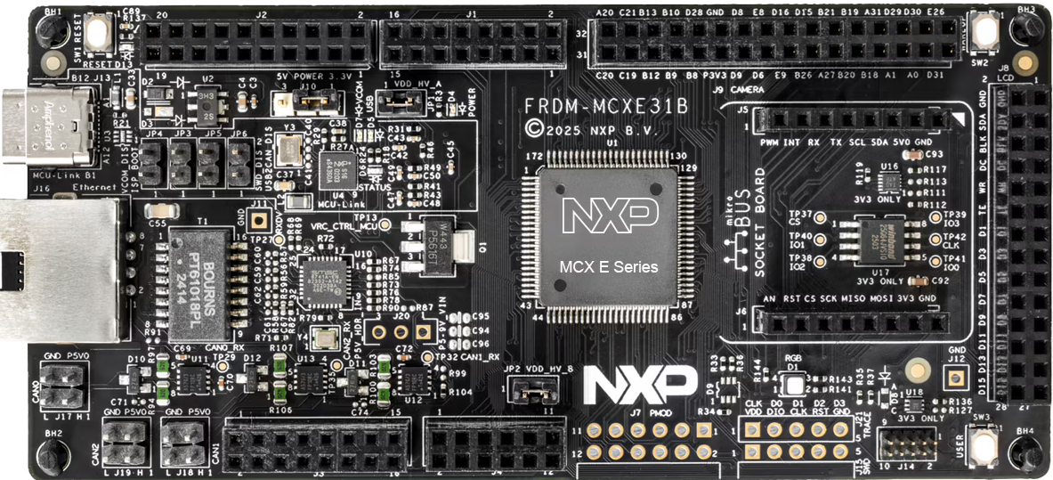
8. Board Setup#
For this example we will be using MCXE31B Freedom board. For getting familiar with the board, visit this link.
Ensure your MCXE31B Freedom board is configured as follows:
J-Link Connection: Connect J-Link debugger to the board
UART Connection: Connect UART cable to the appropriate COM port. In our case, we connected USB to UART converter to pins PTA2 and PTA3
Power: Ensure the board is properly powered via USB
9. Program Signed MBI Image#
Now let’s program the signed MBI image to the device:
# Erase flash region
%! blhost $BLHOST_CONNECT flash-erase-region $APP_ADDRESS 0x40000

# Program signed MBI image
%! blhost $BLHOST_CONNECT write-memory $APP_ADDRESS $SIGNED_MBI
blhost -p COM21 flash-erase-region 0x400000 0x40000
Response status = 0 (0x0) Success.
blhost -p COM21 write-memory 0x400000 workspace/mcxe31_mbi.bin
Writing memory
Response status = 0 (0x0) Success.
Response word 1 = 19596 (0x4c8c)
10. Verify Image Signature#
Finally, let’s verify that the image signature is valid using the HSE firmware:
# Verify image signature using HSE
%! nxpele -f mcxe31b $BLHOST_CONNECT hse img-verify -a $VERIFY_ADDRESS
nxpele -f mcxe31b -p COM21 hse img-verify -a 0x00400fC0
Boot Data Image verification successful
11. Test the Application#
After programming the signed image, you can:
Reset the board to start the application
Check the LED behavior - the red LED should blink according to the application logic
The signed MBI container ensures that:
Only authenticated firmware can run on the device
The image integrity is verified during boot
The HSE firmware validates the signature before execution
Summary#
This example demonstrated the complete flow for MCXE31 basic secure boot:
Device Preparation: Initialized flashloader and verified communication
Key Provisioning: Enrolled and set the ADKP key for secure operations
MBI Creation: Generated a signed Master Boot Image
Image Programming: Programmed signed images to internal flash
Signature Verification: Used HSE firmware to verify the image signature
The secure boot process ensures that only properly signed firmware can execute on the MCXE31 device, providing a foundation for a secure system.